Rules of meshes in Specfem3D
For built-in mesh generator, we can modify DATA/meshfem3D_files/Mesh_Par_file to define regions, meshes and materials.
Define coordinates
First we define limits of X, Y and Z directory.
LATITUDE_MIN                    = -20000.0
LATITUDE_MAX                    = 20000.0
LONGITUDE_MIN                   = 0.0
LONGITUDE_MAX                   = 120000.0
DEPTH_BLOCK_KM                  = 120.0
UTM_PROJECTION_ZONE             = 11
SUPPRESS_UTM_PROJECTION         = .true.
LATITUDErepresentsYdirectory.LONGITUDErepresentsXdirectory.DEPTH_BLOCK_KMdefines maximum depth of the SEM domain in km.
Note
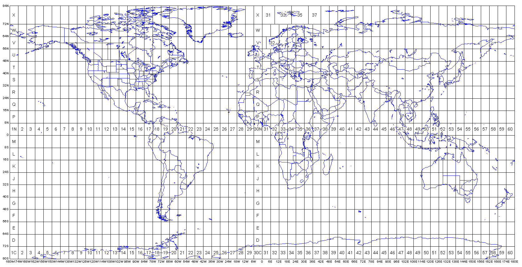
When SUPPRESS_UTM_PROJECTION is set to .false., the UTM_PROJECTION_ZONE is activated. The map of UTM zone can be referred as following. In this case, the LATITUDE and LONGITUDE are true latitude and longitude in degree.
Set elements and materials
Number of elements
# number of elements at the surface along edges of the mesh at the surface
# (must be 8 * multiple of NPROC below if mesh is not regular and contains mesh doublings)
# (must be multiple of NPROC below if mesh is regular)
NEX_XI                          = 24
NEX_ETA                         = 8

NPROC_XI                        = 2
NPROC_ETA                       = 2
NEX_XI: Number of elements alongXdirectory.NEX_ETA: Number of elements alongYdirectory.NPROC_XIandNPROC_ETArepresent number of MPI processors along xi and eta, respectively. TheNPROCin thePar_fileshould beNPROC_XI*NPROC_ETA.
Note
If USE_REGULAR_MESH is set to .true., number of elements must be multiple of NPROC. Otherwise, number of elements must be multiple of 8.
Interface and elements along depth directory
Set number of layers in first effective line. For each interface, we set parameters of interface file as
# SUPPRESS_UTM_PROJECTION  NXI  NETA LONG_MIN   LAT_MIN    SPACING_XI SPACING_ETA
.true.                     2    2    0.0        -20000.0   120000.0   40000.0
interf_1.dat
The interface denotes the top of layer.
Number of
interf_1.datmust beNXI*NETA.
Then set up number of elements for each layer NZ.
Materials of elements
Define properties of materials as
# #material_id  #rho  #vp  #vs  #Q_Kappa  #Q_mu  #anisotropy_flag  #domain_id
1  2920  6500  3850  9999. 9999.  0  2
2  3423  8060  4530  9999. 9999.  0  2
Then assign materials to elements
NREGIONS                        = 2
# define the different regions of the model as :
#NEX_XI_BEGIN  #NEX_XI_END  #NEX_ETA_BEGIN  #NEX_ETA_END  #NZ_BEGIN #NZ_END  #material_id
1            24              1             8            18           25          1
1            24              1             8            1            17          2
Avoid numerical dispersion
The size of meshes is closely correlated to stability of numerical solution in forward modelling. There are two key points to avoid numerical dispersion.
1. Wavelength of seismograms
The size of the elements must be smaller than the minimum possible wavelength in the region.
In the setting above, we assume the \(v_{min}=6500\ m/s\), where the \(v_{min}\) is the Vp of the first layer. The wavelength is defined by the frequency of source time function. In the SEM-FK mode, the frequency \(f=2.0\ Hz\) is defined in FKMODEL with f0. So the maximum size of element should be less than \(3.25\ km\).
If the size of each element bas been determined as 5 km. the maximum frequency should be less than \(\frac{v_{min}}{L}=1.3\ Hz\).
Gaussian Factor and cutoff frequency
A Gaussian low pass filter can be expressed as in frequency domain
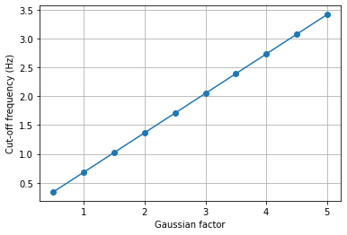
where \(f\) is the physical frequency, \(\alpha\) is the Gaussian Factor. As the Monteiller et al. [2021] suggestion, the so called cut-off frequency can be defined as that corresponding to that the energy of the source spectrum drops to values lower than 1 per cent of the maximum.Therefore, the normalized cutoff frequency is
the correspondence between Gaussian Factor and cutoff frequency is
2. Sampling rate
As a introduction to choosing the time step in user manual, the condition of time step DT in Par_file is
where \(C\) is the so-called Courant number and \(\Omega\) denotes the model volume. The distance \(h=\frac{L}{N_{GLL}}\) depends on the mesh element size and the number of GLL points (defaults to 5). The Courant numbers empirically chosen \(C\approx0.3\).
Note
If you used the mesher
xmeshfem3Dto generate your mesh, you should set the value suggested inOUTPUT_FILES/output_mesher.txt file, which is created after the mesher completed.
 ***
 *** Maximum suggested time step for simulation =    0.04837248
 ***